Products ==> MLC Series LCD Module
Products
MLC Series LCD Module
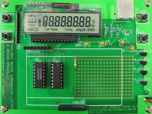
Fig 1.0 Our Static LCD Module Demo Kit
ML1001 static LCD COG (chip on glass) driver which is 40 segments LCD driver with gold bump. It can be cascaded to form a single piece of 80 or 120 segments LCD drivers. It targets at custom TN LCD COG Module product which requires the best quality of TN LCD technology. With the use of ML1001 series driver, it offers the best contrast, the widest viewing angle, the widest range of operating voltage and operating temperature when compared to the multiplex method. Mu-Tron is now offering any kind of Custom Made COG LCD Module using our ML1001 COG Driver.
Our ML1001 includes an internal 32kHz oscillator, a 40-bit shift register, a 40-bit data register, a 16-bit segment driver, a 24-bit segment driver, two common drivers, a blink control circuit, a power-up reset circuit and a frequency divider which offer the necessary clock signals for Blink control, segment & common driver circuit.
Through the DIN pin, the display data is serially shifted into the 40-bit shift register at the rising edge of DCLK signal. The display data, which is going to be displayed on the attached LCD, is then stored in the 40-bit data register at the rising edge of the LOAD signal.
Other features like blinking of the display data by the BEN and BCLK, disable the internal oscillator by the OEN, input an external clock signal to the FIN, and enable or disable the segment and common driver by the SEN1, SEN2, CEN1A and CEN1B, are included.
Features
※ A Gold Bump Chip without external component.
※ Logic & LCD power supply: 2.0V to 6.0V
※ Typical Current consumption: 25uA at VIN = 3V & no load condition.
※ Number of segments: 40
※ Cascade the ML1001 to form a single piece of 80 or 120 segments LCD driver.
※ Simple 3 pin micro controller interface through DIN, DCLK & LOAD.
※ Blink of the display data.
※ Offer best contrast and widest viewing angle of TN LCD technology.
※ No temperature compensation needed for Topr = -40 degree Celsius to 80 degree Celsius.
©Copyright 2005 Mu-Tron Company Ltd